· 4 ·
Mrs. Oliver’s Chair
GREGORY J. LANDREY
In 1732, John Smibert painted Mrs. Andrew (Mary Fitch) Oliver of Boston and her baby, Andrew (fig. 1). The fashionably dressed Mrs. Oliver sits in a chair of distinctive design, with part of its vase-shaped splat and yoke crest visible in the background. The pattern was a standard offering of Boston chairmakers at the time (fig. 2), although this portrait is the only surviving example by Smibert in which it appears. Some thirty years later, John Singleton Copley depicted John Hancock (see fig. 9) seated in a similar Boston Queen Anne side chair with a compass seat and cabriole legs. These images by two noted Boston artists suggest that chairs of this specific type were an enduring form for several decades, and modern research by many furniture historians has confirmed their popularity in Boston and the surrounding area.1
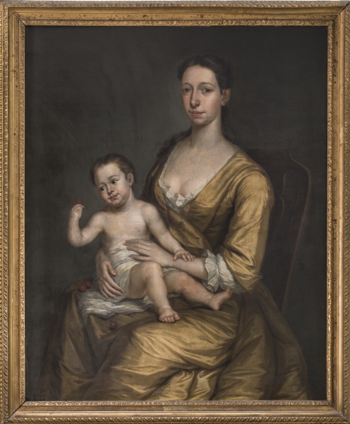
FIG. 1. Mrs. Andrew Oliver and Son, John Smibert (1688–1751), Boston, 1732. Oil on canvas; h 50½, w 40½. Private collection. Photo, Gavin Ashworth.
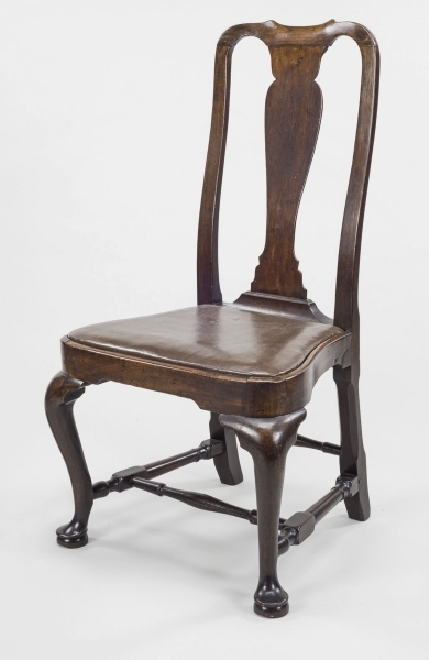
FIG. 2. Side chair, Boston, 1740–65. Black walnut, soft maple; h 40, w 21⅝, Seat d 17¼. Winterthur Museum; Bequest of Henry Francis du Pont (1954.0523).
Their appeal to eighteenth-century Bostonians, we can surmise, was based on several cogent characteristics. The form is a delight to the eye, relying heavily on line, shape, negative space, and volume for its visual success, rather than on ornament. It is graceful and pleasing from all angles, for it is based on the unbroken S shape (“cyma curve”) used for the cabriole (“horse-bone”) leg, knee brackets, seat rails, curved stiles (“crook-back”), and solid vasiform splat, all crowned with a yoke-shaped crest rail.2 These features produce a curvilinear symphony that comes together in a manner that was not previously known or experienced in Boston (figs. 3, 4). The chairs also conformed to the human body in ways that earlier seating furniture did not. The attractiveness of the form and the degree of comfort it provided the sitter certainly contributed to its initial acceptance and its endurance in the mid-eighteenth century, as well as its revived popularity in modern times.3 Although precedent existed for the chair’s individual components, it is the unique combination and refinement of the elements, executed with a simplicity of line, that make them a distinctly Boston-area form.4
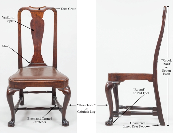
FIG. 3. Glossary of chair terms, identified on the chair in fig. 2.
FIG. 4. Glossary of chair terms, identified on the chair in fig. 2.
In addition to their graceful curvilinearity, these chairs possess other distinguishing features. The compass seat, as opposed to straight rails or simply rounded corners, uses fully developed cyma-curved side rails that flow from the rear of the chair to a swell around the front legs and into a slightly convex front seat rail.5 The solid seat rails are rabbeted to receive the slip seat, rather than having an applied retaining bead, as was occasionally used elsewhere. The form is further defined by its block-and-turned H stretchers, the chamfered edges of the lower section of the stiles and the back of the upper stiles, and a cutaway on the inner surface at the bottom of the rear feet.6 The block-and-turned H stretchers are admittedly a holdover from earlier turned chairs in this otherwise new design. American black walnut (Juglans nigra) is the wood most commonly used for this form.
Many chairs examined in person by the author, as well as measurements of chairs in published sources, indicate a significant consistency in the dimensions and construction of the form. The depth of the seat, from the outer edge of the front seat rail to the back edge of the rear seat rail, tends to measure 17 inches; the width of the compass seat frame from rail to rail is between 20 and 21 inches; and the back width ranges from about 14¾ to 15¼ inches, with the stiles parallel to each other.7
Several construction features typify the form. For example, the mortise-and-tenon joint at the forward end of the side stretcher is most often cut to the full height of the originating stock rather than to the height of the thin neck of the vase shape of the final turning (fig. 5). The two rear stiles are generally parallel, without any splay.8 The side profiles of the crook-back stiles of three chairs in the collection of Winterthur Museum, for example, are virtually the same, despite almost certainly being made in the shops of three different Boston-area chairmakers (fig. 6).
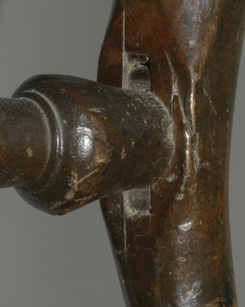
FIG. 5. Mortise-and-tenon joint securing side stretcher to front leg on the chair pictured at center in fig. 6 (1998.0007). The mortise and tenon of this joint are laid out and cut when the chair parts are still in block form, prior to turning the stretchers.
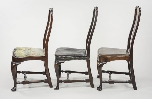
FIG. 6. Profiles of three chairs, Boston, 1730–65. Black walnut, maple. All: Winterthur Museum. Left: h 38¾, w 22⅛, Seat d 17. Bequest of Henry Francis du Pont (1958.2219). Center: h 39½, w 22, Seat d 17¼. Museum purchase with funds provided by Mr. and Mrs. George M. Kaufman, Mr. Martin E. Wunsch and an anonymous donor (1998.0007). Right: see fig. 2.
The consistent dimensions, construction, and form of these chairs, fashioned by several different Boston craftsmen, suggest at least two things: a common adherence to principles of proper proportion shared by many craftsmen and an interconnected trade community. (It is almost as though the chairmakers in Boston all read the same article from Fine Woodworking magazine.) Written documents, such as bills and account books, can help us decipher the arcane and archaic terminology used to describe these chairs, calculate their original cost, and glean other insights into the nature of artisanal work in the period. Nevertheless, such written sources have their limitations, since many aspects of any craft process go unrecorded. The surviving chairs are thus important three-dimensional primary documents that help us understand the mind and methods of the eighteenth-century chairmaker. To better comprehend the methods, the author constructed a pair of these chairs using period techniques and tools (see fig. 28, below). That experience on the shop floor, as a supplement to examining period examples, helped inform the conclusions presented here about how these chairs were most easily and efficiently made in the eighteenth century.
Chairs were commonly made in sets of six or more, rather than one at a time, and thus craftsmen needed to work quickly and economically, repeating processes whenever possible. Once a supply of walnut or other cabinet-grade timber was secured, the chairmaker used a frame saw to cut blocks from the planks for multiple chairs. Each block was of sufficient dimension to allow for proper shaping. The front legs for this chair form were first cut into blocks measuring approximately 3 inches by 3 inches by 18 inches, from which the maker would cut and shape cabriole legs with round or turned pad feet after the joinery was completed. The side rails were initially fashioned from stock measuring 2 inches by 3 inches by 14 inches to allow for the cyma curve of the compass seat and tenons on either end. Similarly, the stock for the front rail might be 2½ inches by 3 inches by 16 inches, the rear rail 2 inches by 1 inch by 14 inches, the rear stiles approximating 1⅝ inches by 4¾ inches by 40 inches, and the crest rail 3 inches by 17 inches by 2 inches. Planning for the joinery could begin once the blocks were rough cut to sufficient size.
One defining tool of the chairmaker was the marking gauge (fig. 7). As Joseph Moxon describes in the third edition of Mechanick Exercises, or the Doctrine of Handy-Works (1703): “Its office is to gage [gauge] a line parallel to any straight side. It is used for Gaging Tennants [tenons].”9 The track of the marking gauge is almost certainly visible on any chair from this period (fig. 8) as evidence of the starting point for laying out the joinery on blocked-up sections that became the legs, stiles, rails, stretchers, crests, and splats. The marking gauge established the location and dimension of the mortises and tenons, the essential components of joined wooden objects, prior to cutting the joints and subsequent shaping. Because it is guided by a fence and functions by moving in a straight line, the marking gauge determined that the tenon would be parallel to the longest dimension of the part that it is integral to, such as the seat rails (fig. 9).
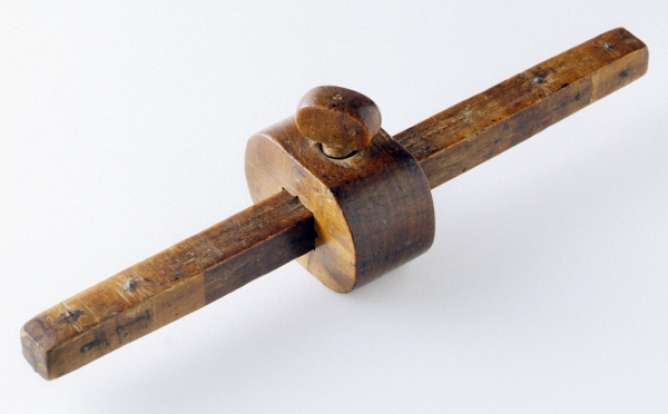
FIG. 7. Marking gauge, Nathaniel Dominy IV (1737–1812), East Hampton, N.Y., 1765. Iron, beech, hickory; h 2½, w 9¾, d 2⅜. Winterthur Museum; Museum purchase with funds provided by Henry Belin du Pont (1957.0026.028).
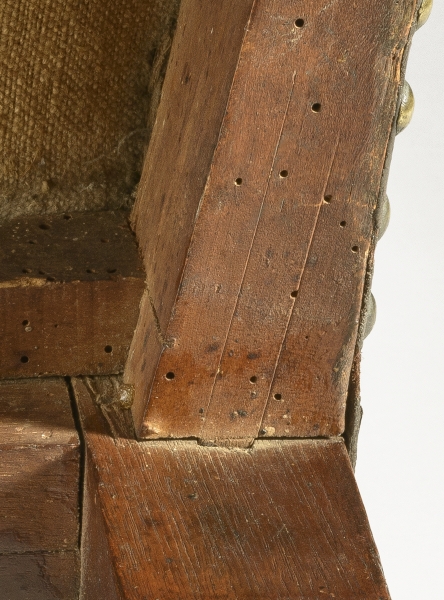
FIG. 8. Mortise-and-tenon joint with layout lines of marking gauge on the chair pictured in the center of fig. 6 (1998.0007). View from beneath side seat rail at joint with rear leg.
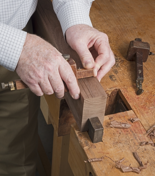
FIG. 9. Laying out a tenon with a marking gauge. Photo, Winterthur Museum.
The craftsman conceived of the object first as blocks of wood, in part because the marking gauge, the starting point for all handwork construction, requires a straight edge. He began by using patterns to transfer the shape of each chair part onto the blocks (fig. 10). With the shapes drawn on the wood surface, the chairmaker was able to determine the location of each set of mortise-and-tenon joints.
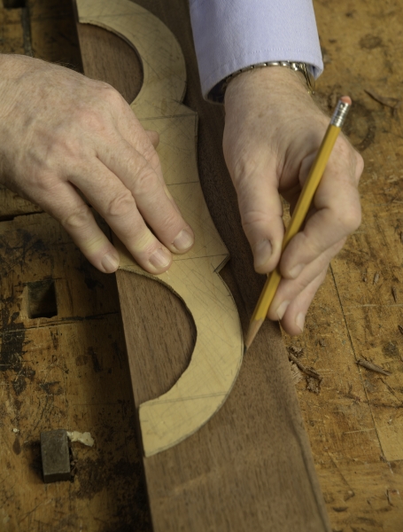
FIG. 10. Tracing outline of crest rail with a pattern. Photo, Winterthur Museum.
The marking gauge was then used to scribe the lines that defined the pairs of mortises and tenons. The two points on the marking gauge were set to the width of the mortising chisel (see fig. 9). The chairmaker would proceed to place the chisel precisely between the lines established by the marking gauge, striking it with a mallet to chop out the mortise (fig. 11). A tenon saw was used to cut the ends, shoulders, and face of the tenon following the lines of the same marking gauge, ensuring a snug fit of tenon into mortise.
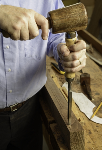
FIG. 11. Chopping mortise with a mortising chisel. Photo, Winterthur Museum.
Tools that function by moving in a straight line, such as a marking gauge, bench plane, and chisel, and the straight-grain nature of wood itself work together toward the swift and efficient construction of chairs that are linear in design. However, these Queen Anne chairs are anything but linear. The precise joining, cutting, and shaping of the curved seat rails in a compass seat chair are more labor intensive and take more skill, than executing the linear components of a straight-sided chair. Chopping mortises at a 90-degree angle is a skill that a tradesman develops so that it becomes instinctive. Both the trapezoidal and compass seat forms of seating furniture are based on seat rails that are joined at an angle either greater than or less than 90 degrees at the front and rear. Such work may require a jig to guide the mortising chisel and regulate the angle of the cut, particularly when speed and accuracy are essential, as in the construction of a set of chairs. Such was the case for the mortises of compass-seat chairs; the mortises and tenons in the rear stiles and front legs are at an obtuse angle to the plane at the back and at an acute angle to the plane of the front. Although the same is true for standard chairmaking, the process for a compass-seat chair is particularly complex because the lower stretchers and the seat rails intersect the stiles at precise, yet slightly different, angles. The angle of the cyma-curved side seat rails to the back of the chair is 15 degrees greater than the angle of the turned side stretchers (fig. 12). That is not the case with a trapezoidal seat chair, whose stretchers and seat rails are at identical angles for both sets of mortises, making the cutting of the joints and subsequent assembly simpler and less labor intensive than for a compass-seat frame.
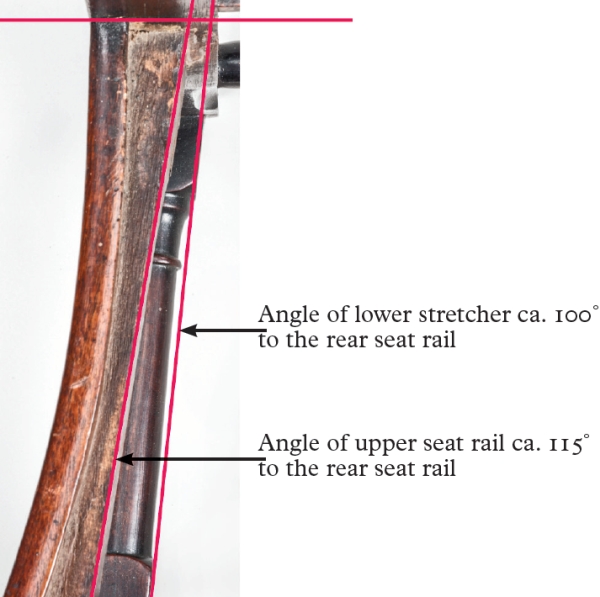
FIG. 12. Angles of joints where side stretcher and side seat rail meet rear leg of the chair in fig. 2.
Like patterns for shapes, jigs are essential for the precise and rapid layout and execution of compound joints. Cutting obtuse and acute compound tenons on both ends of the turned side stretchers requires a repeatable and accurate system, just as is necessary for mortises. The craftsman presumably marked the tenons on the stretcher stock with a marking gauge and cut only the face of the tenons before turning the decorative portions on a lathe. Once the turning was complete, the stretchers were placed in a jig and the compound joints for the tenons’ shoulders were cut (fig. 13).10 This system would allow the maker to cut multiple, interchangeable stretcher cheek joints, recognizing that the left and right stretchers are side specific (fig. 14).
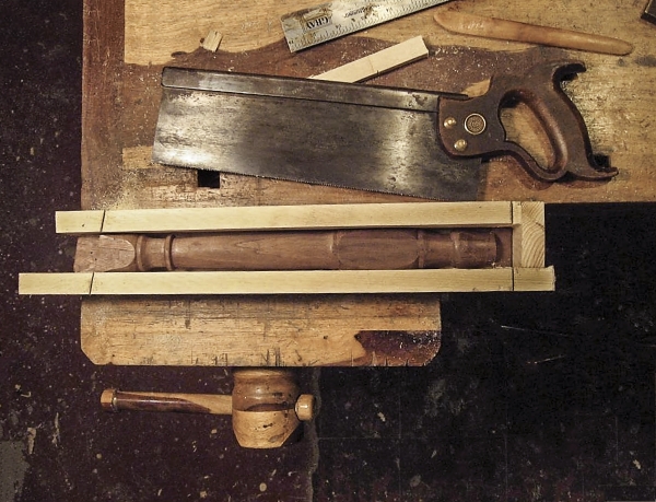
FIG. 13. Jig for cutting end of side stretcher at correct angle. Photo, Gregory J. Landrey.
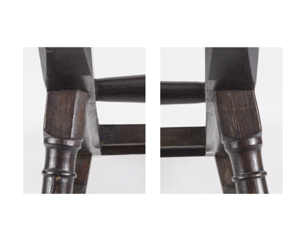
FIG. 14. Angles of rear joints for right and left stretchers of the chair in fig. 2.
After all the mortises and tenons were cut, typically eighteen per chair, the maker could temporarily assemble the chair into block form (fig. 15) for the final fitting of the joints, a crucial step. The mortised-and-tenoned parts were then disassembled and the shaping of the components was begun.
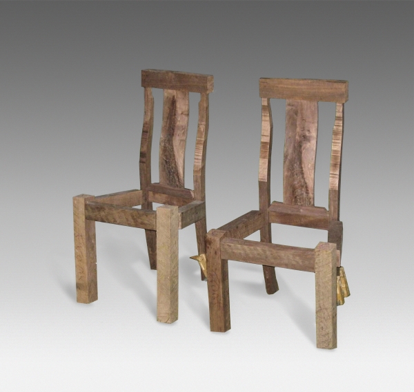
FIG. 15. Reproduction chairs during construction process. Photo, Gregory J. Landrey. See fig. 28 for a completed version of one of these chairs.
Patterns guided the shaping of key elements, including the crest rail, rear stiles, front legs, and compass seats, as well as the initial placement of the joints discussed above. Though patterns used by Boston craftsmen have not survived, examples by Samuel Wing in Sandwich, Massachusetts, and the Dominy family of East Hampton, Long Island, document the practice during the late eighteenth and early nineteenth centuries.11 For the chairs in question here, the craftsman might have used as many as eight patterns for these components (fig. 16).
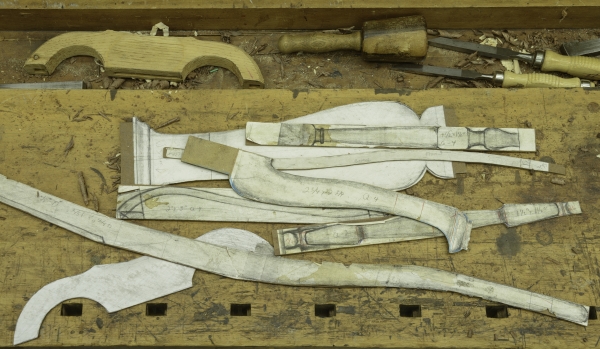
FIG. 16. Modern patterns for making reproduction chairs. Photo, Winterthur Museum.
To begin the process of shaping, the maker used a stylus or pencil to trace the outline of each part onto the wood. The parts were then cut to the rough shape with a frame saw, the workhorse of the shop (fig. 17).12 A single plank may have been wide enough to accommodate multiple stiles, referred to as “nesting,” but if not, stock for the stretchers could be cut from the waste. Ganging parts together for the shaping process increased efficiency and accuracy. The chairmaker relied on a rasp, spokeshave, and, as a final step, a cabinet scraper to sculpt the curves.
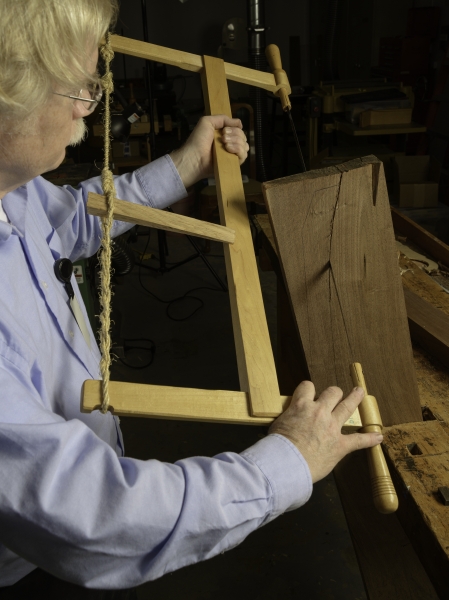
FIG. 17. Cutting out rear stile with a frame saw. Photo, Winterthur Museum.
The yoke-shaped crest rail is one of the defining aspects of this chair form; it is also the most delicate structurally. X-rays of two chairs in the Winterthur collection (fig. 18) suggest that the maker chopped the mortises quickly and reveal how close the mortise ceiling and wall are to the outer surface of the crest rail. The maker must have chopped the mortises while the stock was in block form, since any attempt to do so after shaping would have broken through the crest rail.
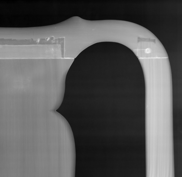
FIG. 18. X-ray of crest rail of the chair in fig. 2.
The crest rail, with the mortises cut previously to receive the tenons from the stiles, was shaped into a yoke form from the 3 inch by 17 inch by 2 inch block. To accomplish this task, the craftsman secured the piece in a bench vise by temporarily attaching a piece of scrap wood to the underside of the crest rail arches, a location that would be cut away once most of the shaping was done (fig. 19). He used a turning saw (a frame saw with a narrow adjustable blade, like a modern coping saw), chisels, rasp, spokeshave, and cabinet scraper to transform the block into a yoke crest rail (figs. 20–23). The two arches on the left and right of the crest were cut out last using a turning saw, with the curve of the arch being finished with a rasp and file. Presumably, two small flats were temporarily kept on either side of the upper outer portion of the crest, looking like ears, to help in the assembly and clamping process. Once the back was assembled with glue and pegs (discussed below), the earlike protrusions were cut off, and the shaping of the crest was completed by blending the stiles and crest into one form.
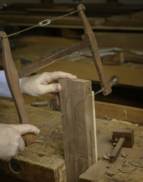
FIG. 19. Cutting out crest rail with a turning saw. Photo, Winterthur Museum.
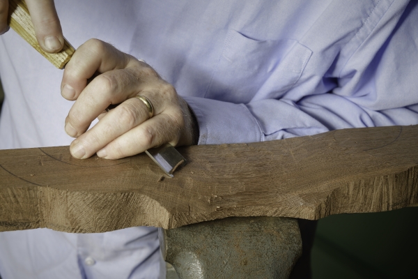
FIG. 20. Shaping crest rail with a chisel. Photo, Winterthur Museum.
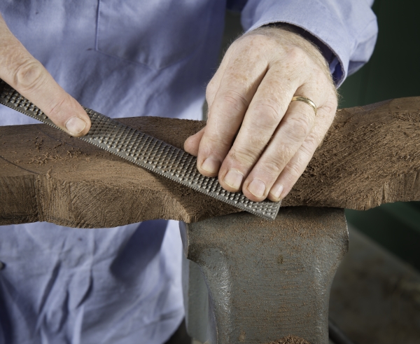
FIG. 21. Shaping crest rail with a rasp. Photo, Winterthur Museum.
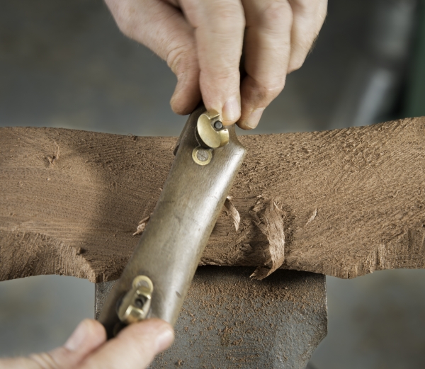
FIG. 22. Shaping crest rail with a spokeshave. Photo, Winterthur Museum.
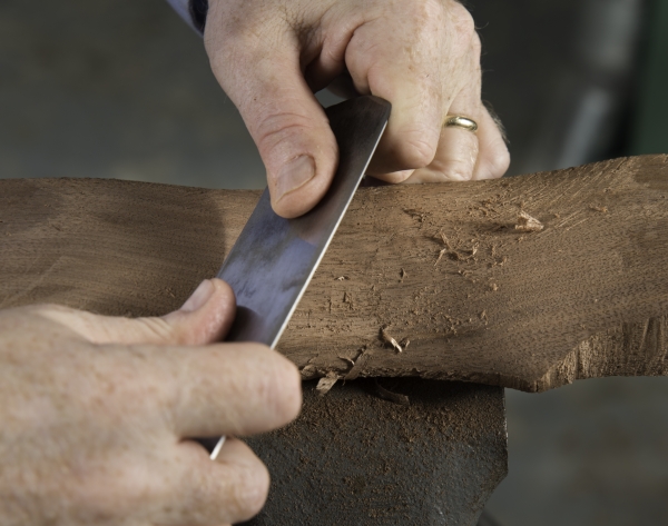
FIG. 23. Shaping crest rail with a scraper. Photo, Winterthur Museum. Typically the scraper was the final tool used to create a smooth, crisp edge on a curved surface such as a crest rail.
The horse-bone, or cabriole, legs are the most sculptural component of the chair. Only the pad foot was turned on a lathe (figs. 24, 25); the rest of the leg was shaped on the bench with the rasp, spokeshave, and cabinet scraper. The cyma curve that defines the horse-bone shape was formed by using a turning saw to cut out the profile traced from the pattern and then shaping the surface with hand tools. The ankle of the leg, just above the joint of the side stretcher, was shaped until it was round in cross section and about 1¼ inches thick. The upper portion of the leg, where the mortises for the seat-rail tenons are housed, was left temporarily in partial block form to facilitate assembly and the gluing phase of construction.
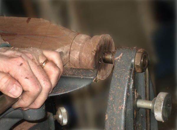
FIG. 24. Turning foot of a chair leg on a lathe. Photo, Winterthur Museum.
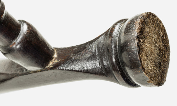
FIG. 25. Turned foot of the chair in fig. 2.
The curved form of the slip-seat frame was precisely shaped with the same tools. Most of the cyma curve of the seat rails was executed on the bench after the tenons were cut, prior to assembly. Some shaping to complete the compass-seat form and slip seat was necessary after final assembly, particularly at the tops of the front legs, as discussed below (fig. 26). Each of the steps required to craft the compass seat demanded a higher level of skill and was more labor intensive than creating the straight rails of a trapezoidal seat, which can be quickly laid out with a straight edge and dressed with a hand plane. The payoff for the extra effort and skill is the beauty and feel of the compass seat (fig. 27).
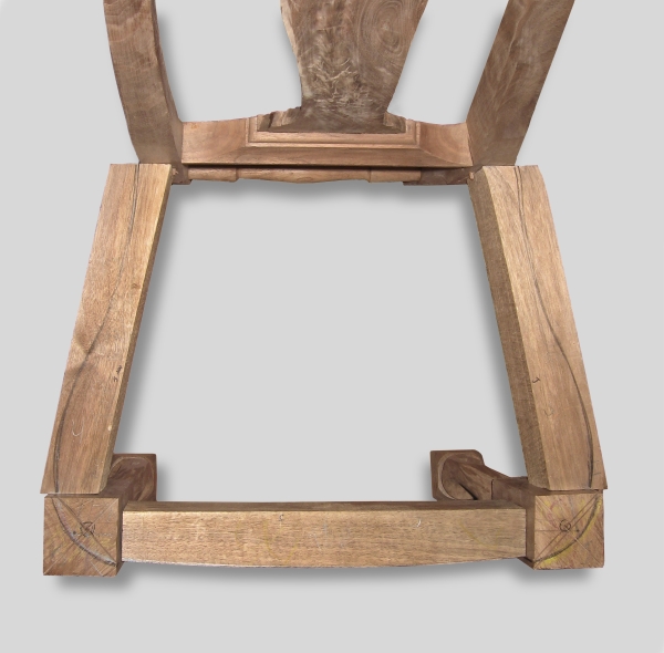
FIG. 26. Seat of the reproduction chair in fig. 28 during construction. Private collection. Photo, Gregory J. Landrey.
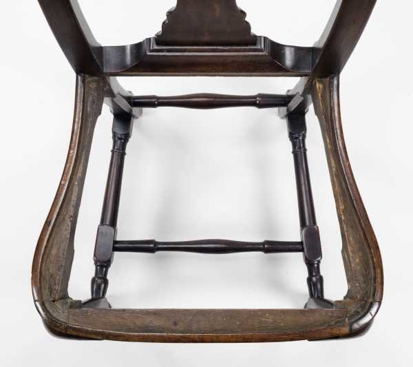
FIG. 27. Seat of the chair in fig. 2.
These chairs consistently have pegs that secure almost every mortise-and-tenon joint. Typically, these pegs do not perforate the interior of the seat frame. Instead, they more often stop just short of exiting the back side of the joint, or they protrude slightly. The visible heads of the pegs on the exterior of the chair are irregular in cross section, but more round than not. The pegs also pulled the joint tight during assembly.
A residue of glue is detectable near joinery on some of the chairs, suggesting that it was used in their original construction. Hide glue, a protein-based adhesive derived from the bone, sinew, tendons, and skin of animals such as cattle or horses, was readily available in an agrarian society. This material requires heat and water to be activated, and it was the adhesive of choice for cabinet- and chairmakers alike. In 1703, Joseph Moxon cautioned: “Your glew must be very warm, for then it is thinnest, and as it chills it thickens: With a small Brush you must smear the Glew well upon the Joint of each piece you are to Glew together.”13
The chairs were assembled in two units, which were then glued and pegged together to make the complete chair. The back joinery—including the stiles, turned lower stretcher, seat rail, shoe-splat assembly, and crest rail—were glued and pegged together first. Pegs were probably sufficient to pull each joint tight; however, clamps might have been used to align and secure the crest rail and stile joinery. The splat remained unglued, residing in a tongue-and-groove joint in both the crest rail and the shoe (the horizontal member between the rear seat rail and the splat), so that the splat can expand and contract.
The front end was assembled in a similar fashion, using pegs and glue. As noted, the top outer corners of the legs were not fully shaped on the bench. For assembly purposes, a block portion was left temporarily in place at the top of the leg, where the mortises for the seat rails are housed. Once the gluing, pegging, and clamping (if needed) were complete, the extra material on the top outer corners of the leg where the mortises for the side rails are housed was chopped off and shaped with a rasp and cabinet scraper, merging the curve of the side rail with the slightly convex front rail to complete the compass-seat form (see figs. 26, 27). A rabbet was then chiseled and cut into the seat frame resulting in a ½-inch-thick recess to receive the slip seat. The slip seat for the compass-seat chair must follow precisely the profile of the relieved rabbet, allowing room for upholstery, which was often leather. This process required careful attention to a curved line that is replicated by handwork in the slip seat. In contrast, a trapezoidal slip seat can be matched to the recess of the seat rails quickly and precisely with a hand plane.
The crispness of the edges of the chair as it left the maker’s hands is not known today, after more than two and a half centuries of wear and tear. The hand planing or scraping initially created sharp edges. Did the chairmaker, with a highly sculptural form such as this, leave the edges just as the edge tools left them? Or was an effort made to dull the corners slightly? We don’t know. The physical evidence required to answer these questions does not survive any more than the true color of a transient dye exists on an aged textile. A hand plane, passing over agreeable wood and cutting in the direction of the grain, will leave the smoothest surface of any technique, either modern or preindustrial. Other than portions of the stiles, however, few of the curvilinear surfaces of these chairs lend themselves to a final treatment with a hand plane. The curves encountered throughout the chair, as noted, require the use of a rasp, spokeshave, and cabinet scraper, often working with challenging grain directions. The result is sufficiently smooth to the touch, yet different from the silky quality that can be achieved on even fussy-grain curved wood using 600-grit sandpaper in a twenty-first-century shop. Although subtle, the fresh feel of the tooled curved walnut surfaces that emanated from a chairmaker’s shop in 1740 must have been altogether unlike the softer contours present today after years of age and use.
Boston furnituremakers of the mid-eighteenth century could have chosen from several finishing materials: a resin-based coating, described in the period as “varnish,” such as rosin or other natural resins; an oil, most likely linseed oil; beeswax; or a combination thereof. For the pair of chairs re-created for this essay (fig. 28), one coat of a natural resin (shellac) was applied, rubbed with rottenstone, and then covered by an application of beeswax and carnauba wax.14
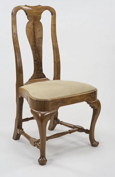
FIG. 28. Reproduction side chair, Gregory J. Landrey (b. 1955), Wilmington, Del., 2013. Black walnut, soft maple; h 40⅛, w 21½, Seat d 17. Private collection. Photo, Winterthur Museum.
The chairs that have been the focus of our attention were not only a fashionable and durable form; their clean, curvilinear lines reflecting the human form were a significant step forward in seating furniture design. Re-creating them using tools and techniques available in the 1730–65 era was useful in furthering our understanding of how furnituremakers solved complex construction problems for a new form typically built in multiples. It is important to recognize that the maker first joined the chair as a blocked-up rectilinear structure, using a marking gauge, mortising chisel, and tenon saw. He then transformed the chair by shaping the elements with a rasp, spokeshave, and cabinet scraper to achieve its defining curvilinear form.
Recognizing the complexity of the engineering, as well as the precision and efficiency of the construction process, enhances our appreciation for the craftsmanship and sophistication of the Queen Anne form. Creating a pair of chairs using preindustrial techniques revealed the labor, engineering, and execution inherent in their design and fabrication. Of necessity, such chairs were costlier than many other types made in the same period. This knowledge helps us understand how the chairs depicted in Mrs. Oliver’s and Mr. Hancock’s portraits were created and suggests why they remain a lasting legacy of design, construction, and craftsmanship.
1. See, for example, Nancy E. Richards and Nancy Goyne Evans with Wendy Cooper and Michael Podmaniczky, New England Furniture at Winterthur: Queen Anne and Chippendale Periods (Winterthur, Del.: Henry Francis du Pont Winterthur Museum, 1997), 14; Benno M. Forman, American Seating Furniture, 1630–1730 (New York: W. W. Norton, 1988), 287; and Brock W. Jobe, “The Late Baroque in Colonial America: The Queen Anne Style,” in American Furniture with Related Decorative Arts, 1660–1830, ed. Gerald W. R. Ward (New York: Hudson Hills Press, 1991), 108.
2. The term horse-bone dates back to the 1680s in England, when it was used to refer to a double-scroll leg; see Adam Bowett, English Furniture, 1660–1714: From Charles II to Queen Anne (Woodbridge, Suffolk: Antique Collectors’ Club, 2002),100–5. The cabriole leg that we associate with the Queen Anne style is a continuous S-curve; in essence it is a double scroll without the abrupt break that occurs in the legs of late seventeenth-century seating furniture. In Early Georgian Furniture, 1715–1740 (Woodbridge, Suffolk: Antique Collectors’ Club, 2009), Bowett states that the cabriole leg of the 1720s and early 1730s was called a French or claw foot, but adds that it seems likely that “the cabriole leg was a development of the baroque scrolled leg or ‘horsebone’, as it was known by English chairmakers” (151). The use of the term “horsebone” appears in the account book of Samuel Grant, a Boston upholsterer, in 1730. It has been assumed that this refers to a cabriole leg, but at that time it had been in use for at least a generation within a British context. For the references to the term in Grant’s account book, see Brock Jobe, “The Boston Furniture Industry, 1720–1740,” in Boston Furniture of the Eighteenth Century: A Conference Held by the Colonial Society of Massachusetts, 11 and 12 May 1972, ed. Walter Muir Whitehill, Jonathan L. Fairbanks, and Brock Jobe, Publications of the Colonial Society of Massachusetts, vol. 48 (Boston: Colonial Society of Massachusetts, 1974), 42.
3. Numerous current furniture retailers offer Queen Anne style–chairs with a yoke crest, including Homestead Furniture and Dutch Crafters. An online Homestead catalogue states: “Treat your guests like royalty with the Queen Anne #500 Dining Chairs” (http://www.homesteadfurnitureonline.com/dining-chairs_queen-anne-500.html), while Dutch Crafters describes its offering as “a classic Queen Anne Dining Chair, it is elegantly formal,” (http://www.dutchcrafters.com/Amish-Queen-Anne-Dining-Room-Chair/p/916). Many authors have provided instructions and measured drawings for making modern reproductions. See, for example, Norman Vandal, Queen Anne Furniture: History, Design, and Construction (Newtown, Conn.: Taunton Press, 1990), 42–51; and Jeffrey P. Greene, American Furniture of the Eighteenth Century (Newtown, Conn.: Taunton Press, 1996), 244–46 and passim.
4. This type of chair had precedents in other lands, including the Netherlands, France, England, and Asia. The horse-bone leg was used on furniture in the Netherlands in the early 1700s and may be a reason that Luke Vincent Lockwood and other early twentieth-century furniture historians referred to the form as being in the “Dutch Style”; see Luke Vincent Lockwood, Colonial Furniture in America, 2 vols. (New York: Charles Scribner & Sons, 1926), 2:57.
The same cyma-curve shaped leg was referred to by the English as a “French foot,” suggesting French origins of the design. The crook-back chair was an early eighteenth-century English form that was often called an “India back,” indicating the influence of South Asia, referencing in particular a solid curved splat joined directly to the yoke-shaped crest and seat rail. Europeans trading with East Asia were exposed to the then-current styles that included curved legs, arms, and aprons of Ming Dynasty Chinese furniture. See also Bowett, Early Georgian Furniture, 150. For the style in general, see Jobe, “Late Baroque in Early America,” 105–13.
5. Boston Queen Anne chairs of this overall design were also made with trapezoidal seats. Customers had an option, just as they did with slip seats or over-the-rails upholstery.
6. Philip D. Zimmerman, “The ‘Boston Chair’ of Mid-Eighteenth-Century Philadelphia,” in American Furniture 2009, ed. Luke Beckerdite (Milwaukee, Wis.: Chipstone Foundation, 2009), 153.
7. Chairs with a carved shell rather than a yoke crest have stiles that may be slightly splayed. As an example, a chair at Winterthur Museum (1958.2219) has a width of 155/16 in. at the top of the back, 15 in. at the plane of the seat rails, and 14¾ in. at the floor, which amounts in total to a splay of only just more than ½ in. from top to bottom.
8. A chair at Winterthur Museum (1958.2219) has a splay of 1 degree.
9. Joseph Moxon, Mechanick Exercises, or the Doctrine of Handy-Works, 3rd ed. (London: Rose and Crown, 1703), 93.
10. The first set of stretcher tenons was cut without the use of a jig, which proved tedious and time consuming. The jig that is mentioned was used further into the project as part of the discovery process. The author is indebted to Allan Breed for suggesting the type of jig that might have been used for cutting stretcher tenons.
11. See Charles F. Hummel, With Hammer in Hand: The Dominy Craftsmen of East Hampton, Long Island (Charlottesville: University Press of Virginia, 1968), 96–100; and Brock Jobe, Gary R. Sullivan, and Jack O’Brien, Harbor and Home: Furniture of Southeastern Massachusetts, 1710–1850 (Lebanon, N.H.: University Press of New England, 2009), 27–29.
12. The author is indebted to Kenneth Meyer for building this reproduction frame saw using a Dominy saw in the Winterthur Museum collection (1957.0026.079) as the model.
13. Moxon, Mechanick Exercises, 105.
14. For an overview of period materials, see Robert D. Mussey Jr., ed., The First American Furniture Finisher’s Manual: A Reprint of “The Cabinet-Maker’s Guide” of 1827 (New York: Dover, 1987).